TECO MAGIC III
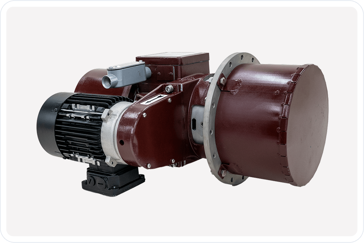
The Magic III measures consistency by drawing a continuous flow of stock past the sensor at a constant velocity. A motor driven propeller provides the steady flow which makes the torque signal insensitive to flow change in the pipe. The consistency sensor is “Outside the Pipe” in a weld on bulb.
Product Summary
Download Product Summary SheetMagic III transmitter measures consistency by sensing the change in sheer force with the rotating sensor. The torque required to turn the Magic III’s rotating sensor varies in proportion to the consistency. As the consistency increases, more torque is required to turn the sensor. Conversely, as the consistency decreases, the less torque is required. The Magic III measures the torque and produces an output proportional to the consistency. This system is faster-responding than a feed back coil system, so the Magic III senses and responds to consistency changes faster than other consistency transmitters.
Magic III’s SMART feature has ten available response curves to match the nonlinear pulp response curves. This gives higher accuracy than traditional linear response curves because it adjusts for higher sensitivity at low consistency and lower sensitivity at higher consistency.
Magic III’s HART feature uses digitally set upper and lower range values. With any HART compatible device, you can program or read the loop’s current output and consistency value anywhere the 4mA to 20mA wires run; from the control room to the transmitter.
The Magic III measures consistency by drawing a continuous flow of stock past the sensor at a constant velocity. The motor driven propeller provides the steady flow so the sensor is immune to velocity changes. Changes in output are, therefore, purely a function of changes in consistency. Also, since the sensor is “outside the pipe”, it doesn’t get damaged by “logs” or anything else in the stock line. The Magic III is long-lasting.
Features & Benefits
- HART Compatiable
- Bi-directional communication enhances diagnostics and configuration and provides quick visibility into the device
- Early warnings and problem detection minimizes impact of deviations and prevents costly shutdowns
- SMART motor driven consistency transmitter
- High sensitivity to consistency changes ensures accurate and responsive measurements
- Velocity immunity eliminates the need for velocity compensation or increasing pipe size
- Self-contained cooling system eliminates the need to run cooling water to the sensor
- Seals lubricated by heat transfer fluid no lubricant required
- Long meter life
- Loop Powered 24 volts
- Simplified wiring requires only one pair of wires for both power and output
- Transmission that outperforms voltage signals over long distances and noisy environments
Applications
Profitability and Product Uniformity via the Consistency Control Chain
Tight basis weight profiles optimize material usage, product uniformity and profitability. Consistency deviations from the Hi-density tower are reflected in basis weight variations. Tightening the basis weight profiles requires minimizing these consistency deviations.
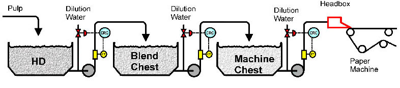
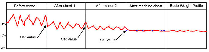
Each transmitter in the “Consistency Control Chain” reduces consistency variation. The cumulative effect of ALL the transmitters working together determines basis weight profile. Contact TECO for a FREE evaluation of your “Consistency Control Chain”. TECO can provide you with consistency solutions you can add right to your bottom line.
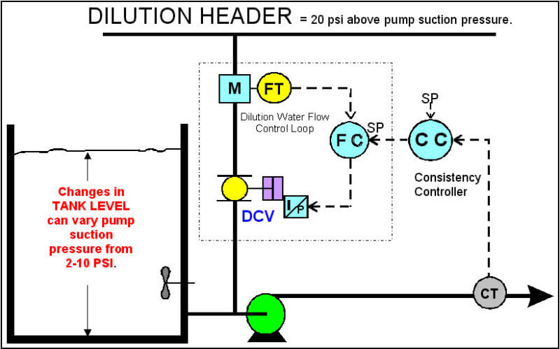
Flow Controlled Dilution, Trim Dilution Only
Flow control is a much better method of controlling dilution water than valve position. It will give tighter consistency control.
WHY?
Changes is dilution header pressure and chest level, effect the amount of water passing through the control valve. Flow control responds faster to pressure changes. Contact us if you want additional information on flow control and how to set up flow control for a HD chest.
Flow Controlled Dilution, Ring and Trim Dilution
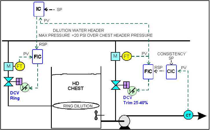
- RSP = Remote Set Point
- SP = Set Point
- IC = This controller has a dead band that keeps DCV Trim valve in its optimum control range.
- CT = Consistency Transmitter
- PV = Process Variable
Consistency Control Chain Evaluation Procedure
Purpose: To identify any equipment or control strategies that would contribute to poor consistency control.
TEST TO BE PERFORMED
1. Manual Bump Test
- Place system in manual control
- Change dilution control valve position by 10 %.
- Return valve to original position
- Put system back in automatic control
- Note Time to Meter Response =Dead Time.
- Note rate of change and time needed to stabilize.
- Note time and rate when valve is returned to original position.
2. Set Point Change (Loop is in Automatic Control)
- Change setpoint by at least 0.2 % consistency
- Return to original setpoint
- Note time to first response = Dead Time
- Time of stabilizing period.
- Rate of change to stabilize.
- Return to original setting.
3. Control Loop Information
- Average Consistency deviation from setpoint ( 2 min. minimum time frame)
- Gain and Reset for each loop
- Dilution Water Header Pressure
- Dilution Control Valve Type and size
- How was size determined
- Injection point and style
4. Sampling Procedures
- How often are samples taken
- By whom
- Test Method
- Sample Valve location & Type of valve
- How are sample results used
Specifications
Download Spec Sheet| Sensitivity | Better than +/- 0.025% as % consistency |
|---|---|
| Consistency | Range adjustments made in % consistency from any HART Protocol adjustment device such as a Meriam TM, RosemountTM (375, 475) SMARTM or Emerson AMS Trex Communicator. Sensing - Standard motor driven disc and shaft to generate torque from consistency changes |
| Pulp Curves | Furnish-specific calibration curve, 1 to 7% installed in transmitter, additional curves available |
| Torque Sensing | Non-Contact Inductive coupling with Stationery Proximity Sensor; approximately .030 in Air Gap |
| Power | 2-wire, 24-29 volts DC, minimum 250 ohm loop resistance |
| Sensing Motor | Standard 3 phase 440 vac @ 60 Hz. Optional 575 vac motor is available |
| Output Signal | 4-20 mA (limited to 23 mA) into 350 ohm max. load @ 24 volts,700 ohms @ 29 volts |
| Output Dampening | Digital 1.5 to 100 seconds (5 sec. factory setting) |
| Output Test Points | 4 to 20 ma. Equal Upper & Lower Range |
| Repeatability | +/- 0.3 % full scale (constant operating conditions) |
| Operating Conditions | Max. stock Temp. 140 °F - Ambient Temp. 140°F. Max. Process Pressure @ 257°F |
| Materials: Wetted Parts | 316 S/S - Housing: Aluminum |
| Seal Cooling | Self-Contained cooling using heat transfer fluid. No external water required |
| MAGIC Ill Upgrade | Can be installed on any existing pneumatic or electronic BTG ® transmitter |
Related Products
TECO MAGIC II
TECO’s Magic II is a loop powered SMART + HART rotating disc shear force consistency transmitter. The transmitter measures consistency by sensing the change in viscosity with a disk rotating in the paper stock.